
Plc Control Panel Wiring Diagram on plc panel wiring diagram Electrical circuit diagram
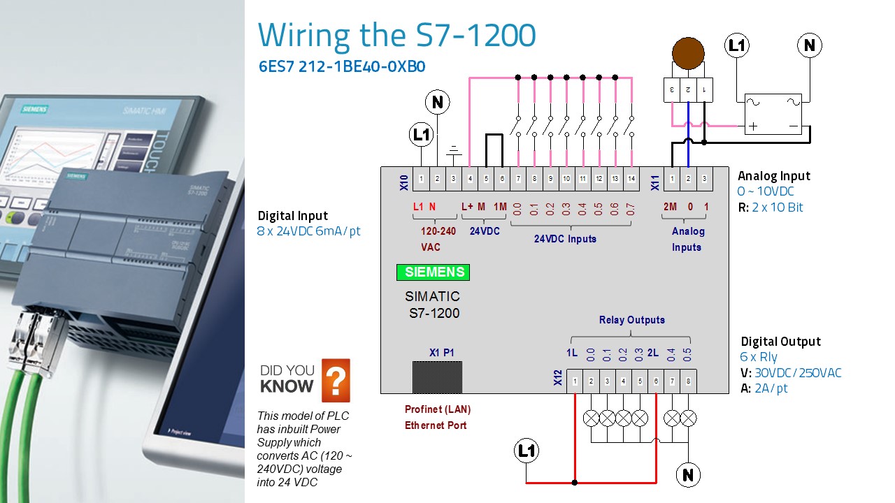
② Removable user wiring connectors (behind the doors) ③ Status LEDs for the on-board I/O ④ PROFINET connector (on the bottom of the CPU) p q s r To communicate with a programming device, the CPU provides a built-in PROFINET port. With the PROFINET network, the CPU can communicate with HMI panels or another CPU. Feature CPU 1212C
Siemens Plc S7 1200 Wiring Diagram Wiring Diagram
November 14, 2023 by Vidya Muthukrishnan Contents What is a PLC? PLC stands for "Programmable Logic Controller". A PLC is a computer specially designed to operate reliably under harsh industrial environments - such as extreme temperatures and wet, dry, and/or dusty conditions.
Simple Plc Wiring Diagram Database
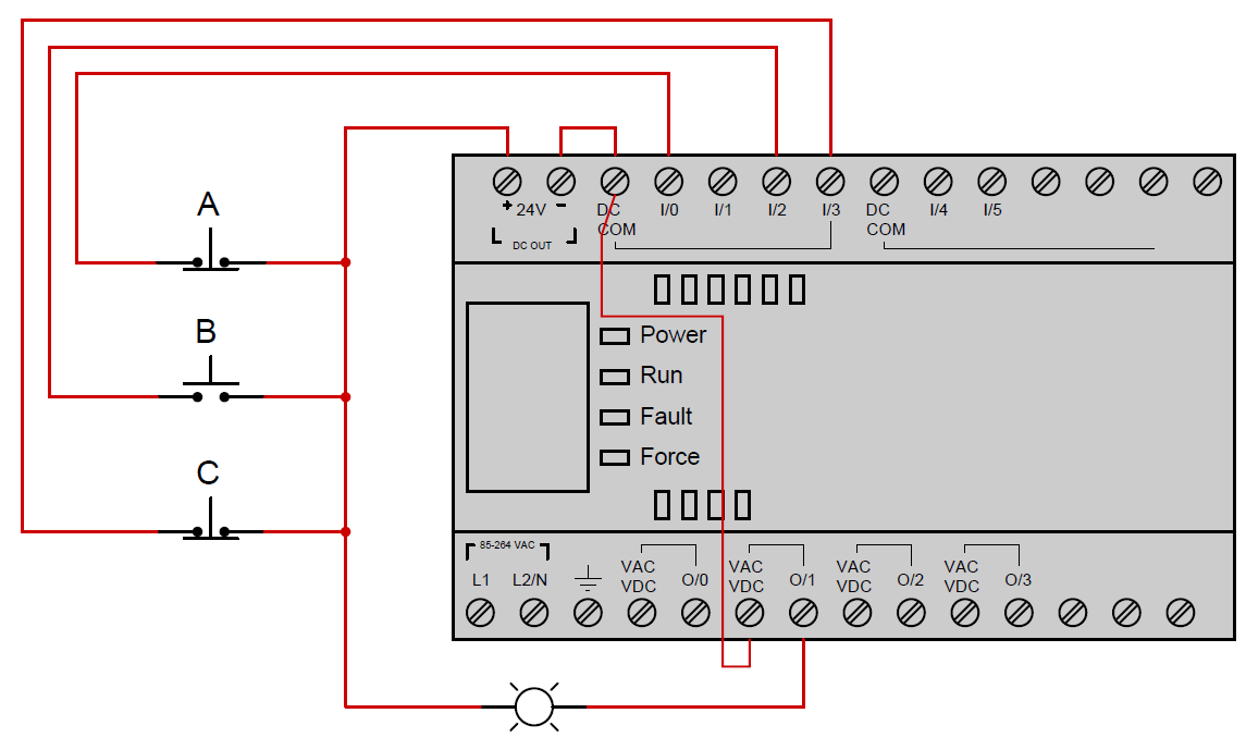
Ladder Logic and Programming PLCs. A PLC has many "input" terminals, through which it interprets "high" and "low" logical states from sensors and switches. It also has many output terminals, through which it outputs "high" and "low" signals to power lights, solenoids, contactors, small motors, and other devices lending.
PLC Ladder Logic Contacts and coils Instrumentation Tools
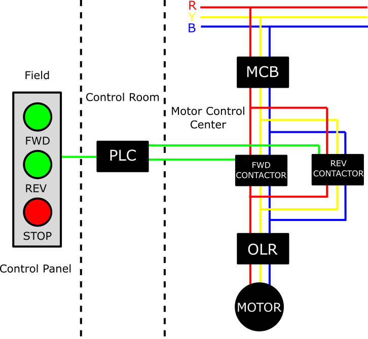
This is the point where the main power supply (3 phases) is connected (R, Y, B, N). It is this point that supplies power to all the components. Install the breaker in such a way that the wireman gets a free hand to do the wiring; because any lag in it can damage the whole system. Busbar
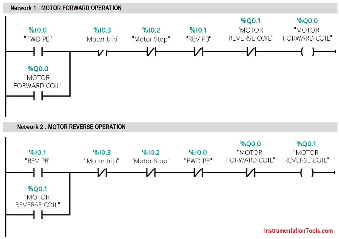
3 Phase Motor Control using PLC Ladder Logic PLC Tutorials Point
PLC wiring diagrams are exact representations of the physical connections between all the devices in a PLC system. The diagrams have been used since the earliest days of PLCs, and they have evolved over time to become much more detailed, precise, and easier to understand.
Wiring Diagram In Plc Wiring Digital and Schematic
To be able to read an electrical wiring diagram of a PLC panel, you should have an understanding of these components. Let's take a look at these two types of electrical components: A) PLC Panel Power Components Rotary Disconnect: It is used for connecting incoming power lines/wires. It can include fuses or not.

Plc Wiring Diagram Guide
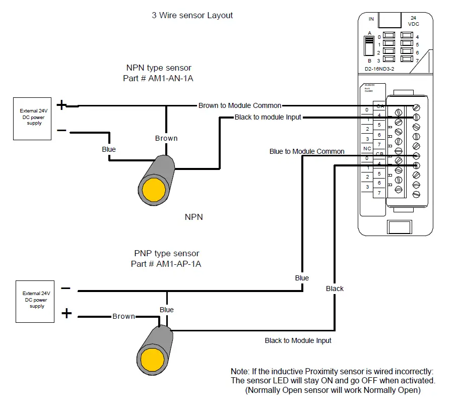
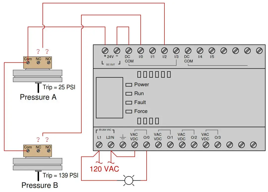
In this article, we are sharing the basic concepts of PLC and DCS control systems Wiring Diagrams for Digital Input (DI), Digital Output (DO), Analog Input (AI), and Analog Output (AO) signals. Note that these diagrams are without a Barrier or isolator, fuses, or surge protector to keep them very simple and understandable.
PLC Wiring Diagrams PLC Digital Signals Wiring Techniques
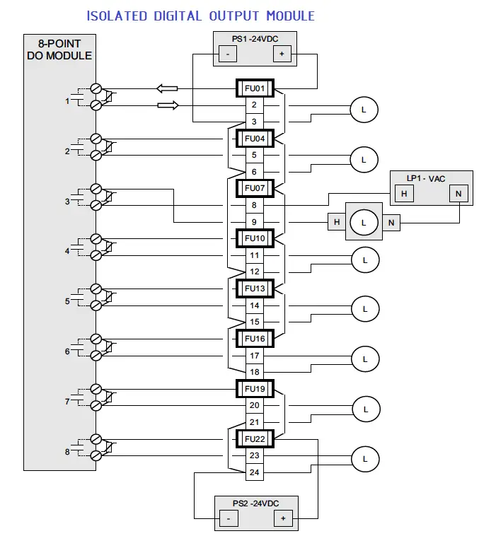
Outputs - digital or analog outputs are controlled by the PLC to a form that can be used to control devices (actuators). PLC inputs. One representation of PLC inputs in wiring diagrams is to divide the inputs into modules and place them on one side. Such a module usually consists of 8 inputs, although there are also 4,16 and 32 inputs or others.
Plc Wiring Diagram Video Wiring Digital and Schematic
Join us here, get awesome perks, and support us, all at once:https://www.youtube.com/c/upmation/joinWhen you look at an industrial control panel wiring dia.

Wiring Diagram For Plc Wiring Diagram and Schematics
C'mon over to https://realpars.com where you can learn PLC programming faster and easier than you ever thought possible!===== Chec.
PLC Wiring Diagrams PLC Digital Signals Wiring Techniques
PLC Control Panel Wiring refers to the process of connecting various electrical components, such as switches, relays, and sensors, to a programmable logic controller (PLC) in order to control and monitor different machinery or processes.
Ab Plc Wiring Diagram Caret X Digital
PLC wiring diagrams are graphical representations of the electrical connections and devices used in a PLC system. They provide a visual guide for technicians and engineers to understand how the different components are connected and how signals flow through the system.
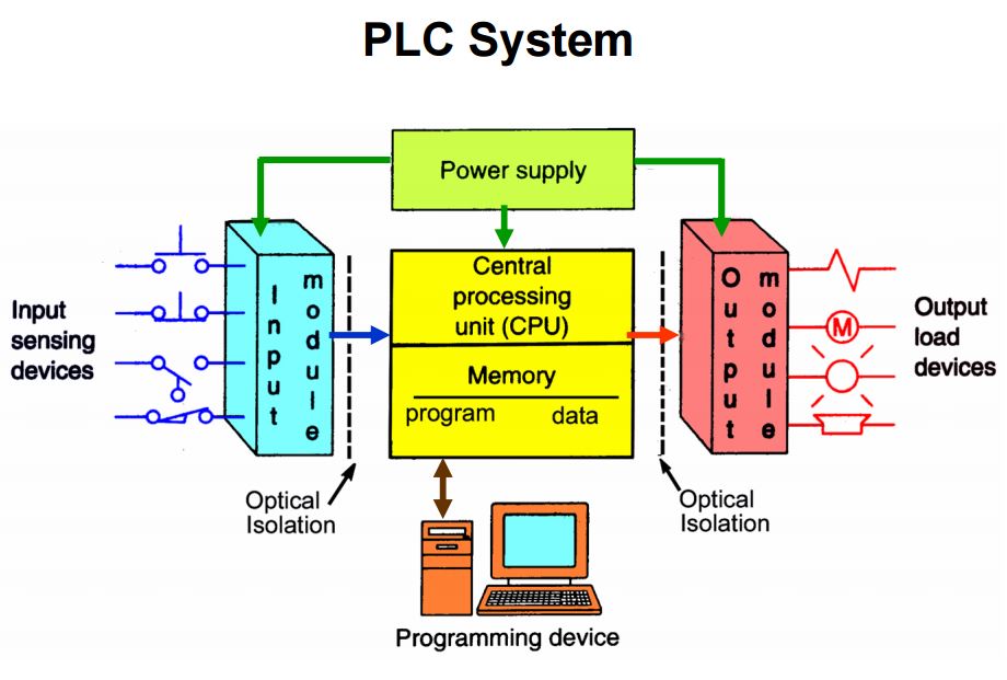
Programmable Logic Controller (PLC) Components Electrical Academia
Join us here, get awesome perks, and support us, all at once:https://www.youtube.com/c/upmation/joinRead the full blog post at https://upmation.com/plc-w.
Ab Plc Wiring Diagram Caret X Digital
Standard duty "START-STOP" stations are provided with the connections "A". shown in the adjacent diagram. This. connection must be removed from all but one of the "START-STOP" stations used. Heavy duty and oiltight push button stations can also be used but they do not. have the wiring connection "A", so it must.
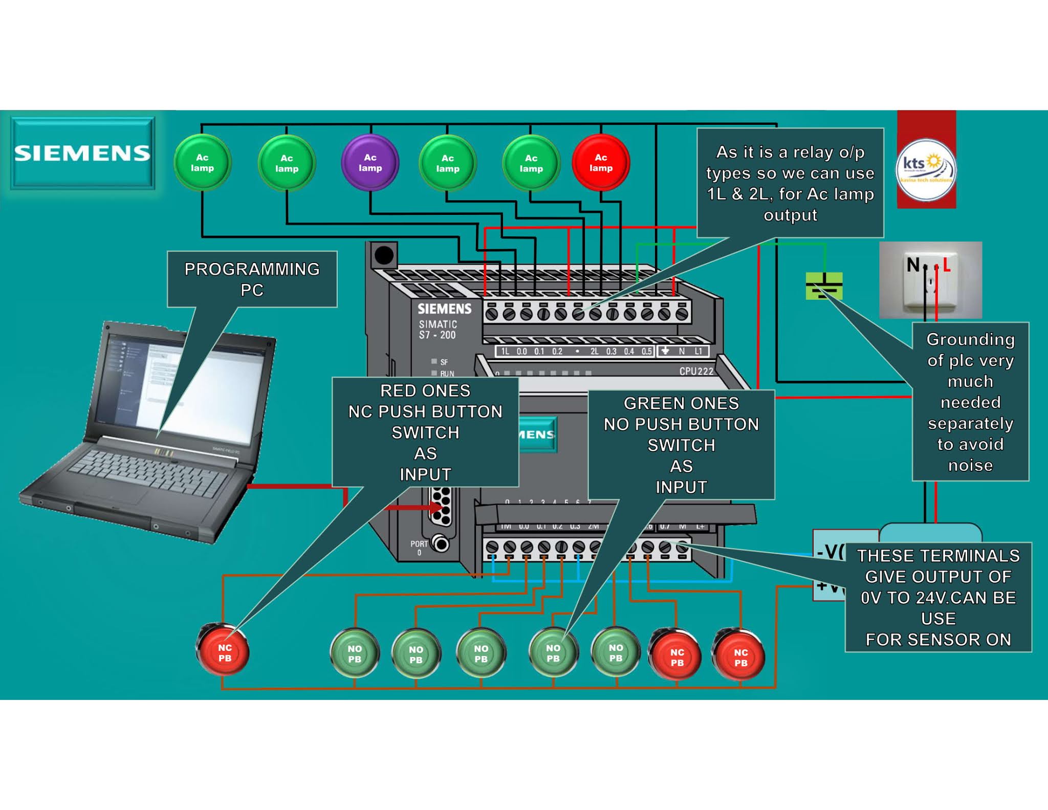
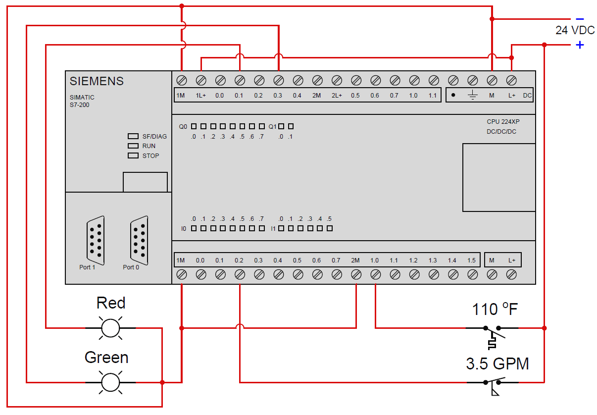
SIEMENS PLC WIRING S7200 PLC WIRING DIAGRAM Kavisa Tech Solutions
Wiring considerations Wire Size Each I/O terminal can accept one or more conductors of a particular wire size. The user should check that the wire is the correct gauge and that it is the proper size to handle the maximum possible current. Wire and Terminal Labeling

Plc Wiring Diagram Examples Wiring Flow Schema
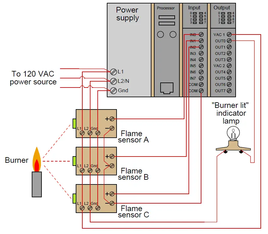
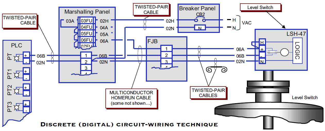
PLC Wiring Diagrams | PLC Digital Signals Wiring Techniques PLC Digital Signals Wiring Techniques by Editorial Staff Ina process plant, on/off control is done through the PLC or DCS. The below Figure is an overview of one discrete/digital (on/off) circuit, showing the entire process from the power supply through the sensor and on to the PLC.